Beams Supported at Both Ends with Continuous and Point Loads: Stress, Deflection, Formulas and Calculators
Supporting loads, stress and deflections.
The bending stress in a bending beam can be expressed as
σ = y M / I (1)
where
σ = bending stress (Pa (N/m2), N/mm2, psi)
y = distance to point from neutral axis (m, mm, in)
M = bending moment (Nm, lb in)
I = moment of Inertia (m4, mm4, in4)
- Beams - Supported at Both Ends - Continuous and Point Loads
- Beams - Fixed at One End and Supported at the Other - Continuous and Point Loads
- Beams - Fixed at Both Ends - Continuous and Point Loads
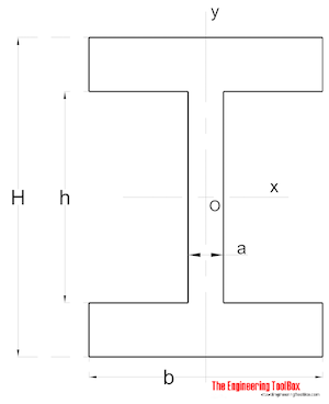
Distance y in a typical steel beam profile.
The calculator below can be used to calculate maximum stress and deflection of beams with one single or uniform distributed loads.
Beam Supported at Both Ends - Uniform Continuous Distributed Load
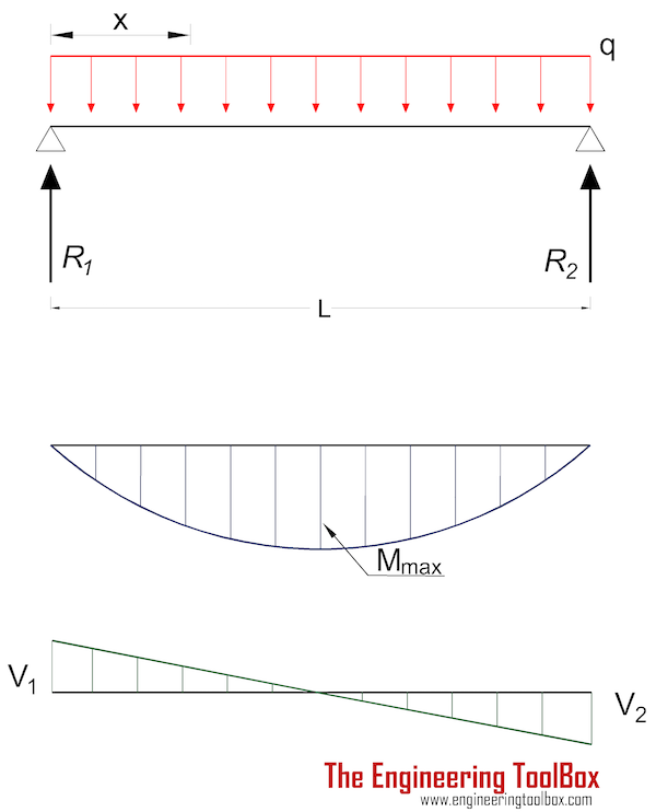
The moment in a beam with uniform load supported at both ends in position x can be expressed as
Mx = q x (L - x) / 2 (2)
where
Mx = moment in position x (Nm, lb in)
x = distance from end (m, mm, in)
The maximum moment is at the center of the beam at distance L/2 and can be expressed as
Mmax = q L2 / 8 (2a)
where
Mmax = maximum moment (Nm, lb in)
q = uniform load per length unit of beam (N/m, N/mm, lb/in)
L = length of beam (m, mm, in)
Maximum Stress
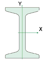
Equation 1 and 2a can be combined to express maximum stress in a beam with uniform load supported at both ends at distance L/2 as
σmax = ymax q L2 / (8 I) (2b)
where
σmax = maximum stress (Pa (N/m2), N/mm2, psi)
ymax = distance to extreme point from neutral axis (m, mm, in)
- 1 N/m2= 1×10⁻⁶ N/mm2 = 1 Pa = 1.4504×10⁻⁴ psi
- 1 psi (lb/in2) = 144 psf (lbf/ft2) = 6,894.8 Pa (N/m2) = 6.895×10⁻³ N/mm2
Maximum deflection :
δmax = 5 q L4 / (384 E I) (2c)
where
δmax = maximum deflection (m, mm, in)
E = Modulus of Elasticity (Pa (N/m2), N/mm2, psi)
Deflection in position x:
δx = q x (L3 - 2 L x2+ x3) / (24 E I) (2d)
Note! - deflection is often the limiting factor in beam design. For some applications beams must be stronger than required by maximum loads, to avoid unacceptable deflections.
Forces acting on the ends:
R1 = R2
= q L / 2 (2e)
where
R = reaction force (N, lb)
Example - Beam with Uniform Load, Metric Units
A UB 305 x 127 x 42 beam with length 5000 mm carries a uniform load of 6 N/mm . The moment of inertia for the beam is 8196 cm4 (81960000 mm4) and the modulus of elasticity for the steel used in the beam is 200 GPa (200000 N/mm2) . The height of the beam is 300 mm (the distance of the extreme point to the neutral axis is 150 mm ).
The maximum stress in the beam can be calculated
σmax = (150 mm) (6 N/mm) (5000 mm)2/ (8 (81960000 mm4))
= 34.3 N/mm2
= 34.3 106 N/m2(Pa)
= 34.3 MPa
The maximum deflection in the beam can be calculated
δmax = 5 (6 N/mm) (5000 mm)4/ ((200000 N/mm2) (81960000 mm4) 384)
= 2.98 mm
Uniform Load Beam Calculator - Metric Units
- 1 mm4 = 10-4 cm4 = 10-12 m4
- 1 cm4 = 10-8 m = 104 mm
- 1 in4 = 4.16×105 mm4 = 41.6 cm4
- 1 N/mm2 = 106 N/m2(Pa)
Uniform Load Beam Calculator - Imperial Units
Example - Beam with Uniform Load, Imperial Units
The maximum stress in a "W 12 x 35" Steel Wide Flange beam, 100 inches long, moment of inertia 285 in4 , modulus of elasticity 29000000 psi , with uniform load 100 lb/in can be calculated as
σmax = ymax q L2 / (8 I)
= (6.25 in) (100 lb/in) (100 in)2/ (8 (285 in4))
= 2741 (lb/in2, psi)
The maximum deflection can be calculated as
δmax = 5 q L4 / (E I 384)
= 5 (100 lb/in) (100 in)4/ ((29000000 lb/in2) (285 in4) 384)
= 0.016 in
Beam Supported at Both Ends - Load at Center
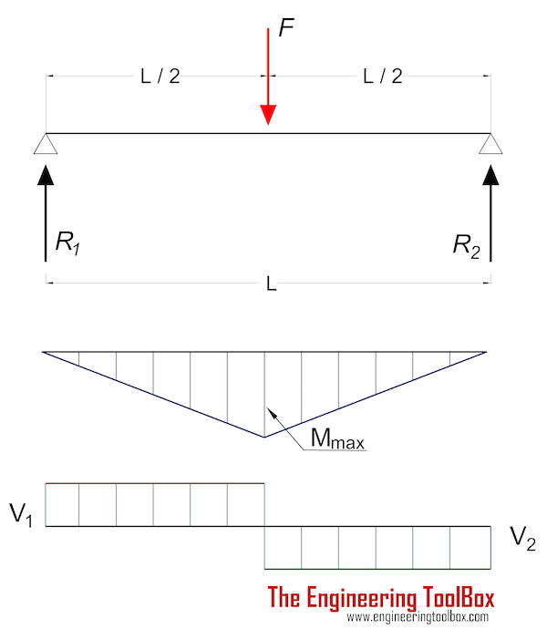
Maximum moment in a beam with center load supported at both ends:
Mmax = F L / 4 (3a)
Maximum Stress
Maximum stress in a beam with single center load supported at both ends:
σmax = ymax F L / (4 I) (3b)
where
F = load (N, lb)
Maximum deflection can be expressed as
δmax = F L3 / (48 E I) (3c)
Forces acting on the ends:
R1 = R2
= F / 2 (3d)
Single Center Load Beam Calculator - Metric Units
Single Center Load Beam Calculator - Imperial Units
Example - Beam with a Single Center Load
The maximum stress in a "W 12 x 35" Steel Wide Flange beam, 100 inches long, moment of inertia 285 in4 , modulus of elasticity 29000000 psi , with a center load 10000 lb can be calculated like
σmax = ymax F L / (4 I)
= (6.25 in) (10000 lb) (100 in) / (4 (285 in4))
= 5482 (lb/in2, psi)
The maximum deflection can be calculated as
δmax = F L3 / E I 48
= (10000 lb) (100 in)3/ ((29000000 lb/in2) (285 in4) 48)
= 0.025 in
Some Typical Vertical Deflection Limits
- total deflection : span/250
- live load deflection : span/360
- cantilevers : span/180
- domestic timber floor joists : span/330 (max 14 mm)
- brittle elements : span/500
- crane girders : span/600
Beam Supported at Both Ends - Eccentric Load
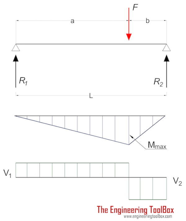
Maximum moment in a beam with single eccentric load at point of load:
Mmax = F a b / L (4a)
Maximum Stress
Maximum stress in a beam with single center load supported at both ends:
σmax = ymax F a b / (L I) (4b)
Maximum deflection at point of load can be expressed as
δF = F a2 b2 / (3 E I L) (4c)
Forces acting on the ends:
R1 = F b / L (4d)
R2= F a / L (4e)
Beam Supported at Both Ends - Two Eccentric Loads
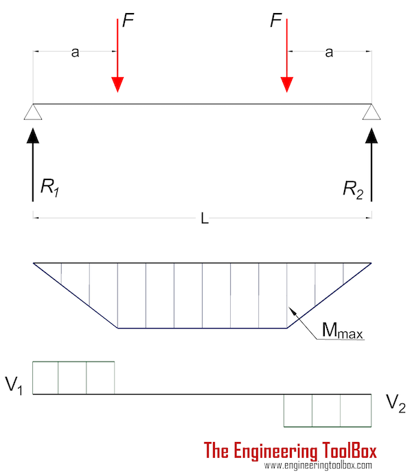
Maximum moment (between loads) in a beam with two eccentric loads:
Mmax = F a (5a)
Maximum Stress
Maximum stress in a beam with two eccentric loads supported at both ends:
σmax = ymax F a / I (5b)
Maximum deflection at point of load can be expressed as
δF = F a (3L2- 4 a2) / (24 E I) (5c)
Forces acting on the ends:
R1 = R2
= F (5d)
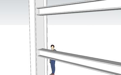
Insert beams to your Sketchup model with the Engineering ToolBox Sketchup Extension
Beam Supported at Both Ends - Three Point Loads
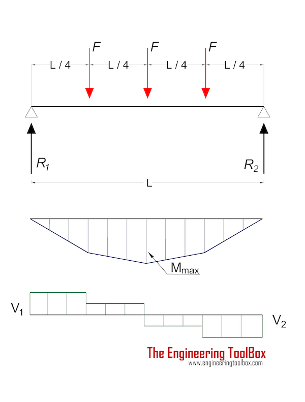
Maximum moment (between loads) in a beam with three point loads:
Mmax = F L / 2 (6a)
Maximum Stress
Maximum stress in a beam with three point loads supported at both ends:
σmax = ymax F L / (2 I) (6b)
Maximum deflection at the center of the beam can be expressed as
δF = F L3/ (20.22 E I) (6c)
Forces acting on the ends:
R1 = R2
= 1.5 F (6d)

