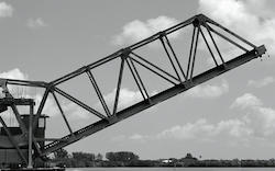
Drawbridge - Force and Moment vs. Elevation
Calculate the acting forces and moments when elevating drawbridges or beams.
Horizontal Beam/Drawbridge
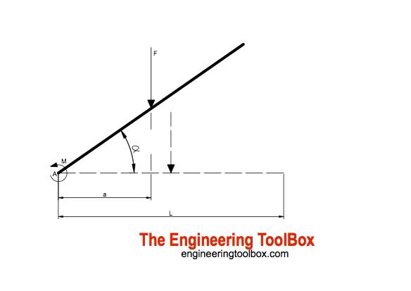
For a beam supported at one end - like a typical drawbridge - the resultant force acting on the bridge can be calculated as
F = q L
= m g L (1)
where
F = resultant force or weight (N)
q = uniform distributed load or weight (N/m)
L = length of beam or bridge (m)
m = continuous distributed mass (kg/m)
g = acceleration of gravity (9.81 m/s2)
For an uniform distributed load the resultant force F will act in distance
a = L / 2 (2)
The moment acting in A can be calculated as
M = F a (3)
= F L / 2 (3b)
Note! The generic eq. 3 can be used for any combination of distributed or point loads.
Example - Moment with Horizontal Beam/Drawbridge
The total weight - or resultant force - of a 10 m HE-B 340B steel beam with continuous mass 134 kg/m can be calculated as
F = (134 kg/m) (9.81 m/s2) (10 m)
= 13145 N
The acting distance a for the resultant force or weight can be calculated as
a = (10 m) / 2
= 5 m
The moment acting in A can be calculated as
M = (13145 N) (5 m)
= 65725 Nm
Elevated Beam/Drawbridge
For and elevated beam or drawbridge the distance between the action force F and the moment in A varies. For a lifting angle the distance can be calculated as
a = cos(α) L / 2 (4)
where
α = lifting angle (degrees)
Eq. 3 for the moment can be modified to
M = F cos(α) L / 2 (5)
Example - Moment for Elevated Beam/Drawbridge
The beam from the example above is lifted 30 degrees. The moment in A can be calculated
M = (13145 N) cos(30 degrees) (10 m) / 2
= 56920 Nm
Elevation Beam/Drawbridge Calculator
Default values are from the examples above where a = L / 2 in horizontal position. The calculator is generic and can be used for any uniform or point load combination as long as the resultant force F and point of action a can be calculated.
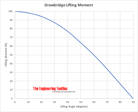
Drawbridge Lifting Moment
Lifting moment (%) related to maximum start moment at elevation 0 degrees.


