Pitot Tubes
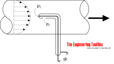
Pitot tubes can be used to measure fluid flow velocities by measuring the difference between static and dynamic pressure in the flow.
A pitot tube can be used to measure fluid flow velocity by converting the kinetic energy in a fluid flow to potential energy.

The principle is based on the Bernoulli Equation where each term of the equation can be interpreted as pressure
p + 1/2 ρ v2 + ρ g h
= p + 1/2 ρ v2 + γ h
= constant along a streamline (1)
where
p = static pressure (relative to the moving fluid) (Pa)
ρ = density of fluid (kg/m3)
v = flow velocity (m/s)
γ = ρ g = specific weight (N/m3)
g = acceleration of gravity (m/s2)
h = elevation height (m)
Each term of the equation has the dimension force per unit area N/m2 (Pa) - or in imperial units lb/ft2 (psi).
Static Pressure
The first term - p - is the static pressure. It is static relative to the moving fluid and can be measured through a flat opening in parallel to the flow.
Dynamic Pressure
The second term - 1/2ρ v2 - is called the dynamic pressure.
Hydrostatic Pressure
The third term - γ h - is called the hydrostatic pressure. It represent the pressure due to change in elevation.
Stagnation Pressure
The Bernoulli Equation states that the energy along a streamline is constant - and can be modified to
p1 + 1/2ρ v12 + γ h1
= p2 + 1/2ρ v22 + γ h2
= constant along the streamline (2)
where
suffix1 is a point in the free flow upstream
suffix2 is the stagnation point where the velocity in the flow is zero
Flow Velocity
In a measuring point we regard the hydrostatic pressure as a constant where h1 = h2 - and this part can be eliminated. Since v2 is zero, (2) can be modified to:
p1 + 1/2 ρ v12 = p2 (3)
or
v1 = (2 (p2 - p1) / ρ) 1/2
= (2 Δp / ρ) 1/2 (4)
where
Δp = p2 - p1 (differential pressure)
With (4) it's possible to calculate the flow velocity in point 1 - the free flow upstream - if we know the differential pressure difference Δp = p2 - p1 and the density of the fluid.
It is common to use head instead of pressure. (4) can be modified by dividing with specific weight γ to
v1 = c (2 g Δh)1/2 (5)
where
c = coefficient - depending on reference liquid and units used or calculated
g = acceleration of gravity
Δh = h2 - h1 = height difference (fluid column)
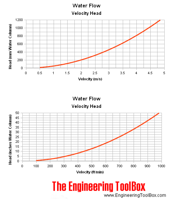
Note! - in the basic equation the head unit is with reference to the density of the flowing fluid. For other units and reference liquids - like mm Water Column - check Velocity Pressure Head.
The Pitot Tube
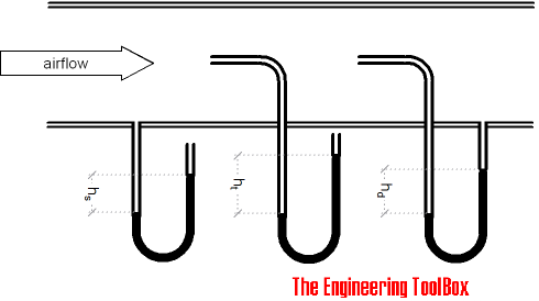
The pitot tube is a simple and convenient instrument to measure the difference between static, total and dynamic pressure (or head).

The head - Δh - (or pressure difference - Δp) can be measured and calculated with the help of u-tube manometers, electronic pressure transmitters or similar instrumentation.
Air Flow - Velocity and Dynamic Head Chart
The charts below are based on air density 1.205 kg/m3 and water density 1000 kg/m3.
Note that as indicated in the diagram above - pitot tubes are not suited for low velocity flow. Due to low dynamic pressure (head) the readings will be inaccurate.
Water Flow - Velocity and Dynamic Head Chart
Flow Metering - Point Velocity Area Method
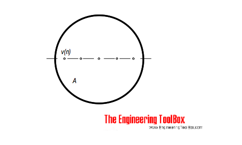
The point velocities in a duct, channel or pipe can be measured by traversing the cross-sectional area of the conduit. The point velocities can be used to calculate the average velocity that can be used to estimate the flow.

The average velocity can be calculated as
va = Σ vn / n
= (2 g Σ hn / n)1/2 (6)
where
va = average velocity (m/s, ft/s)
vn = point velocity (m/s, ft/s)
hn = point height difference pitot meter (m, ft)
n = number of point velocities
The volume flow in the conduit can be calculated as
q = va A (7)
where
q = flow (m3/s, ft3/s)
A = cross-sectional area (m2, ft2)
For round ducts larger than 10 inches the average velocity can be calculated as the arithmetic middle of a 10 point traverse from inward side wall with distance
- 2%, 8%, 15%, 23%, 34%, 66%, 77%, 85%, 92% and 98%
For smaller ducts the the average velocity can be estimated to 81% of centerline velocity.


