Mass Moment of Inertia
The Mass Moment of Inertia vs. mass of object, it's shape and relative point of rotation - the Radius of Gyration.
Mass Moment of Inertia (Moment of Inertia) - I - is a measure of an object's resistance to change in rotation direction. Moment of Inertia has the same relationship to angular acceleration as mass has to linear acceleration.
- Moment of Inertia of a body depends on the distribution of mass in the body with respect to the axis of rotation
For a point mass the Moment of Inertia is the mass times the square of perpendicular distance to the rotation reference axis and can be expressed as
I = m r2 (1)
where
I = moment of inertia ( kg m2, slug ft2, lbf fts2)
m = mass (kg, slugs)
r = distance between axis and rotation mass (m, ft)
Example - Moment of Inertia of a Single Mass

make 3D models with the free Engineering ToolBox Sketchup Extension
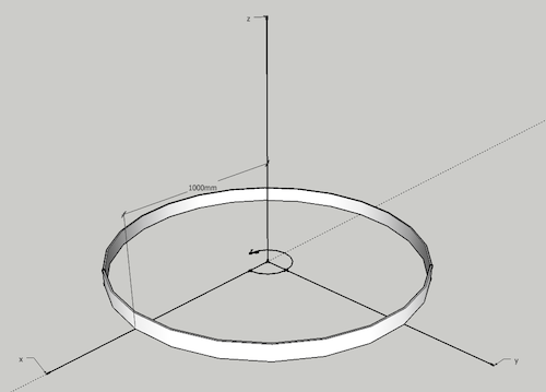
The Moment of Inertia with respect to rotation around the z-axis of a single mass of 1 kg distributed as a thin ring as indicated in the figure above, can be calculated as
Iz = (1 kg) ((1000 mm) (0.001 m/mm))2
= 1 kg m2
Moment of Inertia - Distributed Masses
Point mass is the basis for all other moments of inertia since any object can be "built up" from a collection of point masses.
I = ∑i (mi ri2)
= m1 r12 + m2 r22 + ..... + mn rn2 (2)
For rigid bodies with continuous distribution of adjacent particles the formula is better expressed as an integral
I = ∫ r2 dm (2b)
where
dm = mass of an infinitesimally small part of the body
Convert between Units for the Moment of Inertia
| Multiply with | ||||||
|---|---|---|---|---|---|---|
| from | to | |||||
| kg m2 | g cm2 | lbm ft2 | lbm in2 | slug ft2 | slug in2 | |
| kg m2 | 1 | 1×10⁷ | 2.37×101 | 3.42×10³ | 7.38×10⁻¹ | 1.06×10² |
| g cm2 | 1×10⁻⁷ | 1 | 2.37×10⁻⁶ | 3.42×10⁻⁴ | 7.38×10⁻⁸ | 1.06×10⁵ |
| lbm ft2 | 4.21×10⁻² | 4.21×10⁵ | 1 | 1.44×10² | 3.11×10⁻² | 4.48 |
| lbm in2 | 2.93×10⁻⁴ | 2.93×10³ | 6.94×10⁻³ | 1 | 2.16×10⁻⁴ | 3.11×10⁻² |
| slug ft2 | 1.36 | 1.36×10⁷ | 3.22×101 | 4.63×10³ | 1 | 1.44×10² |
| slug in2 | 9.42×10⁻³ | 9.42×10⁴ | 2.23×10⁻¹ | 3.22×101 | 6.94×10⁻³ | 1 |
Moment of Inertia - General Formula
A generic expression of the inertia equation is
I = k m r2 (2c)
where
k = inertial constant - depending on the shape of the body
Radius of Gyration (in Mechanics)
The Radius of Gyration is the distance from the rotation axis where a concentrated point mass equals the Moment of Inertia of the actual body. The Radius of Gyration for a body can be expressed as
rg = (I / m)1/2 (2d)
where
rg = radius of gyration (m, ft)
I = moment of inertia for the body (kg m2, slug ft2)
m = mass of the body (kg, slugs)
Some Typical Bodies and their Moments of Inertia
Cylinder
Thin-walled hollow cylinder
Moments of Inertia for a thin-walled hollow cylinder is comparable with the point mass (1) and can be expressed as:
I = m r2 (3a)
where
m = mass of the hollow (kg, slugs)
r = distance between axis and the thin walled hollow (m, ft)
ro = distance between axis and outside hollow (m, ft)
Hollow cylinder
I = 1/2 m (ri 2+ ro 2) (3b)
where
m = mass of hollow (kg, slugs)
ri = distance between axis and inside hollow (m, ft)
ro = distance between axis and outside hollow (m, ft)
Solid cylinder
I = 1/2 m r2 (3c)
where
m = mass of cylinder (kg, slugs)
r = distance between axis and outside cylinder (m, ft)
Circular Disk
I = 1/2 m r2 (3d)
where
m = mass of disk (kg, slugs)
r = distance between axis and outside disk (m, ft)
Sphere
Thin-walled hollow sphere
I = 2/3 m r2 (4a)
where
m = mass of sphere hollow (kg, slugs)
r = distance between axis and hollow (m, ft)
Solid sphere
I = 2/5 m r2 (4b)
where
m = mass of sphere (kg, slugs)
r = radius in sphere (m, ft)
Rectangular Plane
Moments of Inertia for a rectangular plane with axis through center can be expressed as
I = 1/12 m (a2+ b2) (5)
where
a, b = short and long sides
Moments of Inertia for a rectangular plane with axis along edge can be expressed as
I = 1/3 m a2 (5b)
Slender Rod
Moments of Inertia for a slender rod with axis through center can be expressed as
I = 1/12 m L2 (6)
where
L = length of rod
Moments of Inertia for a slender rod with axis through end can be expressed as
I = 1/3 m L2 (6b)


