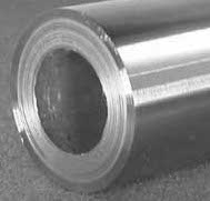
Shafts Torsion
The torsion of solid or hollow shafts - Polar Moment of Inertia of Area.
Shear Stress in the Shaft
When a shaft is subjected to a torque or twisting a shearing stress is produced in the shaft. The shear stress varies from zero in the axis to a maximum at the outside surface of the shaft.
The shear stress in a solid circular shaft in a given position can be expressed as:
τ = T r / J (1)
where
τ = shear stress (Pa, lbf/ft2(psf))
T = twisting moment (Nm, lbf ft)
r = distance from center to stressed surface in the given position (m, ft)
J = Polar Moment of Inertia of Area (m4, ft4)
Note
- the " Polar Moment of Inertia of an Area " is a measure of a shaft's ability to resist torsion. The " Polar Moment of Inertia" is defined with respect to an axis perpendicular to the area considered. It is analogous to the " Area Moment of Inertia " - which characterizes a beam's ability to resist bending - required to predict deflection and stress in a beam.
- 1 ft = 12 in
- 1 ft4 = 20736 in4
- 1 psf (lbf/ft2) = 1/144 psi (lbf/in2)
" Polar Moment of Inertia of an Area " is also called " Polar Moment of Inertia ", " Second Moment of Area ", " Area Moment of Inertia ", " Polar Moment of Area " or " Second Area Moment ".
Polar Moment of Inertia vs. Area Moment of Inertia
- " Polar Moment of Inertia " - a measure of a beam's ability to resist torsion - which is required to calculate the twist of a beam subjected to torque
- " Area Moment of Inertia " - a property of shape that is used to predict deflection, bending and stress in beams
Circular Shaft and Maximum Moment or Torque
Maximum moment in a circular shaft can be expressed as:
Tmax = τmax J / R (2)
where
Tmax = maximum twisting torque (Nm, lbf ft)
τmax = maximum shear stress (Pa, lbf /ft2)
R = radius of shaft (m, ft)
Combining (2) and (3) for a solid shaft
Tmax = (π / 16) τmax D3 (2b)
Combining (2) and (3b) for a hollow shaft
Tmax = (π / 16) τmax (D4 - d4) / D (2c)
Circular Shaft and Polar Moment of Inertia
Polar Moment of Inertia of a circular solid shaft can be expressed as
J = π R4/ 2
= π (D / 2)4/ 2
= π D4/ 32 (3)
where
D = shaft outside diameter (m, in)
Polar Moment of Inertia of a circular hollow shaft can be expressed as
J = π (D4 - d4) / 32 (3b)
where
d = shaft inside diameter (m, in)
Diameter of a Solid Shaft
Diameter of a solid shaft can calculated by the formula
D = 1.72 (Tmax / τmax )1/3 (4)
Torsional Deflection of Shaft
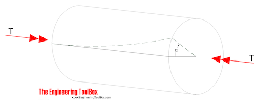
The angular deflection of a torsion shaft can be expressed as
α = L T / (JG) (5)
where
α = angular shaft deflection ( radians)
L = length of shaft (m, ft)
G = Shear Modulus of Rigidity - or Modulus of Rigidity (Pa, psf)
The angular deflection of a torsion solid shaft can be expressed as
α = 32 L T / (G π D4) (5a)
The angular deflection of a torsion hollow shaft can be expressed as
α = 32 L T / (G π (D4 - d4)) (5b)
The angle in degrees can be achieved by multiplying the angle θ in radians with 180 / π.
S olid shaft (π replaced)
αdegrees ≈ 584 L T / (G D4) (6a)
Hollow shaft (π replaced)
αdegrees ≈ 584 L T / (G (D4 - d4) (6b)
Torsion Resisting Moments from Shafts of Various Cross Sections
| Shaft Cross Section Area | Maximum Torsional Resisting Moment - Tmax - (Nm, lbf ft) | Nomenclature | |
|---|---|---|---|
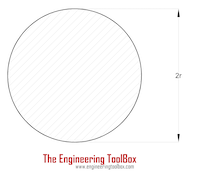 |
Solid Cylinder Shaft |
(π / 16) τmax (2 r)3 = (π / 16) τmax D3 |
|
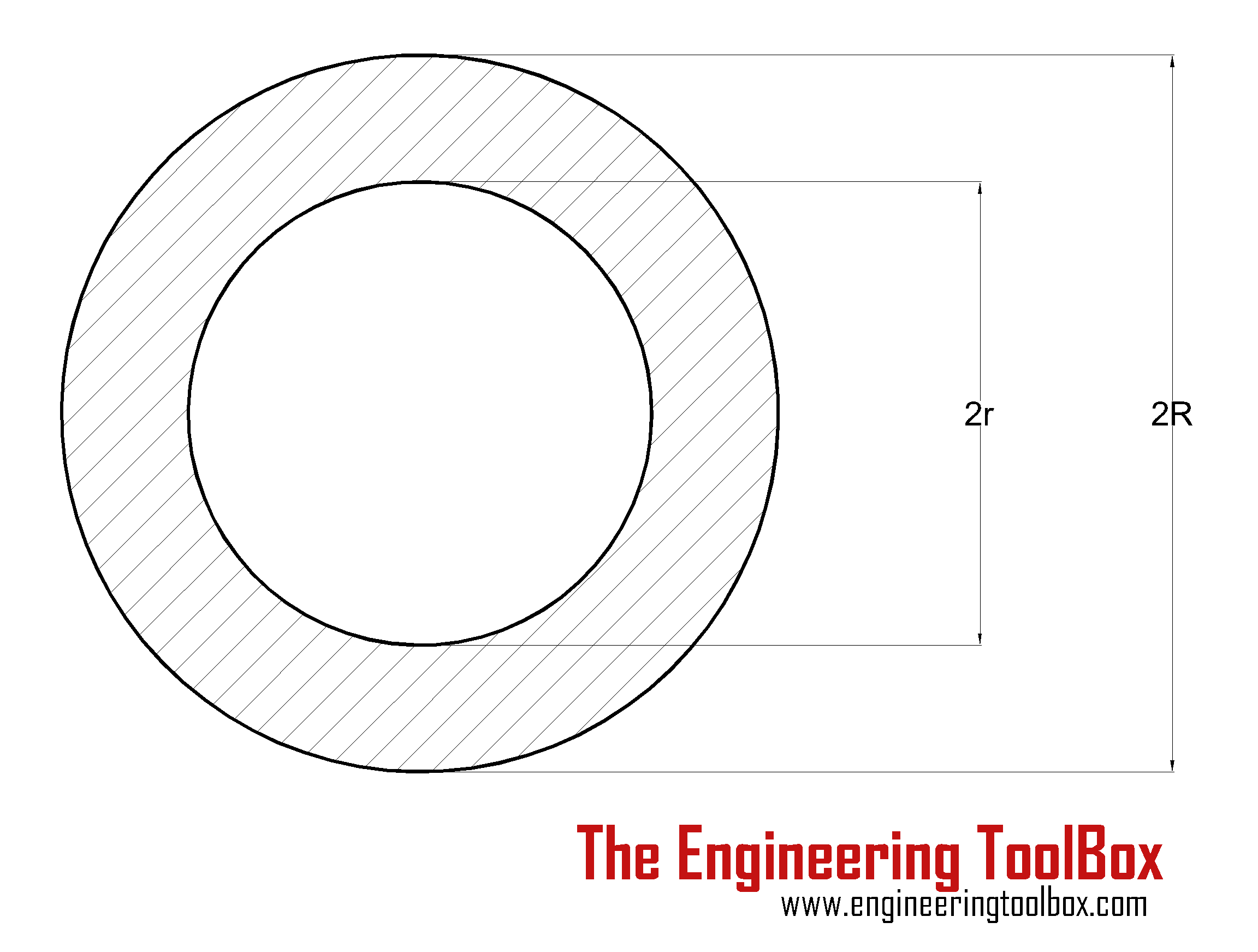 |
Hollow Cylinder Shaft |
(π / 16) τmax ((2 R)4 - (2 r)4) / (2 R) = (π / 16) τmax (D4 - d4) / D |
|
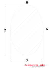 |
Ellipse Shaft | (π / 16) τmax b2h | h = "height" of shaft b = "width" of shaft h > b |
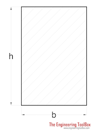 |
Rectangle Shaft | (2 / 9) τmax b2h | h > b |
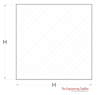 |
Square Shaft | (2 / 9) τmax H3 | |
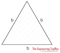 |
Triangle Shaft | (1 / 20) τmax b3 | b = length of triangle side |
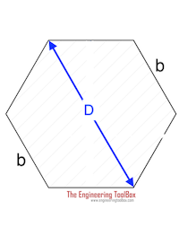 |
Hexagon Shaft |
0.123τmax D3 0.189 τmax b 3 |
|
Example - Shear Stress and Angular Deflection in a Solid Cylinder
A moment of 1000 Nm is acting on a solid cylinder shaft with diameter 50 mm (0.05 m) and length 1 m. The shaft is made in steel with modulus of rigidity 79 GPa (79×109 Pa) .
Maximum shear stress can be calculated as
τmax = T r / J
= T (D / 2) / ( π D4 / 32)
= (1000 Nm) ((0.05 m) / 2) / ( π (0.05 m)4 / 32)
= 40764331 Pa
= 40.8 MPa
The angular deflection of the shaft can be calculated as
θ = L T / (J G)
= L T / ( ( π D4 / 32) G)
= (1 m) (1000 Nm) / ((π (0.05 m)4 / 32) (79×109 Pa))
= 0.021 ( radians)
= 1.2o
Example - Shear Stress and Angular Deflection in a Hollow Cylinder
A moment of 1000 Nm is acting on a hollow cylinder shaft with outer diameter 50 mm (0.05 m) , inner diameter 30 mm (0.03 m) and length 1 m. The shaft is made in steel with modulus of rigidity 79 GPa (79×109 Pa) .
Maximum shear stress can be calculated as
τmax = T r / J
= T (D / 2) / (π (D4 - d4) / 32)
= (1000 Nm) ((0.05 m) / 2) / (π ((0.05 m)4 - (0.03 m)4) / 32)
= 46.8 MPa
The angular deflection of the shaft can be calculated as
θ = L T / (J G)
= L T / (( π D4/ 32) G)
= (1 m) (1000 Nm) / (( π ((0.05 m)4 - (0.03 m)4) / 32) (79×109 Pa))
= 0.023 radian)
= 1.4o
Example - Required Shaft Diameter to Transmit Power
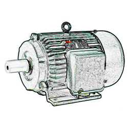
A 15 kW electric motor shall be used to transmit power through a connected solid shaft. The motor and the shaft rotates with 2000 rpm . The maximum allowable shear stress - τmax - in the shaft is 100 MPa .
The connection between power and torque can be expressed
P = 0.105 nrpm T (7)
where
P = power (W)
nrpm = speed of shaft (rpm)
Re-arranged and with values - the torque can be calculated
T = (15×103 W) / (0.105 (2000 rpm))
= 71 Nm
Minimum diameter of the shaft can be calculated with eq. 4
D = 1.72 ((71 Nm) / (100×106 Pa))1/3
= 0.0153 m
= 15.3 mm

