Equivalent Length Method - Minor Pressure Loss in Piping Systems
Calculate minor pressure loss in piping systems with the Equivalent Pipe Length Method.
An efficient and simple way to calculate the pressure loss in a piping system is the "Equivalent Pipe Length Method".
1. Make a Diagram of the Piping System
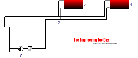
Make a diagram where the system is structured with nodes as shown below.

In the very simply circulating system used in this example the first node (0) is the pump. The next node is the tees (2) where the piping system splits up. The other nodes are the heating radiators.
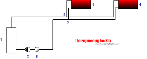
In many systems the structure can be simplified as above since the piping in both directions are of same size. If a more fine grained approach is required, additional nodes can be added in both directions as shown below.

2. Make a calculation table
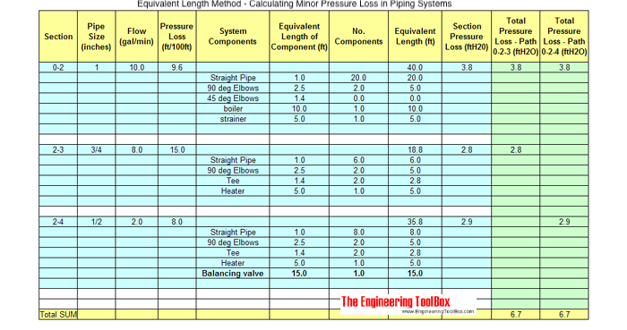
With the most simplified nodes structure above a calculation table can be made as shown below. Each section from node to node is calculated by supplying length, volume flow, pipe size, pressure loss from diagrams or tables for the actual pipes and components in the sections and their individual equivalent length substituting the the minor loss.

An excel template with the table above can be downloaded here:
Note! The flow and pressure units must be adjusted to the data available for your piping system.
3. Add Volume flow, Pipe Size and Pressure Loss for each Section
Add actual pipe size and in each section. Use tabulated data or a diagrams.
The pressure loss may alternatively be calculated with the Hazen-Williams Equation or the Darcy-Weisbach Formula.
- Pressure loss for many types of pipes can be found here.
4. Add Equivalent Length of all Valves, Fittings and Straight Pipes
Add the equivalent length of all valves, components, fittings and straight pipes in the sections.
5. Summarize the Pressure Loss in each Section
Calculate and summarize the pressure loss in each section.
6. Summarize the Pressure Loss in all Paths
Finally, add up the pressure loss in all sections that form unique paths. In the example above there are two unique paths - one is section 0 - 2 - 3, the other is section 0 - 2 - 4. Add extra columns for additional paths in more complicated systems.
The highest pressure loss determines the pump head.
7. Add Balancing Valves
Add valves where it is necessary to balance the system. In the example above a balancing valve is added in section 2-4.
Note! The Equivalent Pipe Length Method can be adapted to most piping systems - like water supply systems, gravity heating systems and similar.


