Copper Tubes - Heat Losses
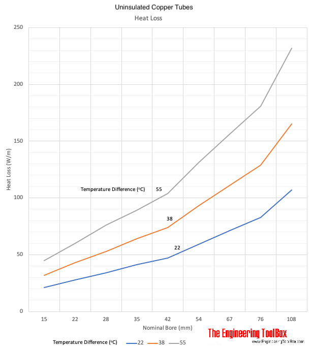
Heat loss from uninsulated copper tubes vs. temperature differences between tube and air.
Values from the table below can be used to indicate the heat losses from uninsulated copper pipes:
Nominal bore | Heat Loss | ||||||
---|---|---|---|---|---|---|---|
(W/m) | (Btu/hr ft) | ||||||
Temperature difference (oC) | Temperature difference (oF) | ||||||
(mm) | (inches) | 22 | 38 | 55 | 40 | 68 | 99 |
15 | 1/2 | 21 | 32 | 45 | 22 | 34 | 47 |
22 | 3/4 | 28 | 43 | 60 | 29 | 45 | 53 |
28 | 1 | 34 | 53 | 76 | 36 | 56 | 79 |
35 | 1 1/4 | 41 | 64 | 89 | 43 | 67 | 93 |
42 | 1 1/2 | 47 | 74 | 104 | 49 | 77 | 108 |
54 | 2 | 59 | 93 | 131 | 62 | 97 | 136 |
67 | 2 1/2 | 71 | 111 | 156 | 74 | 116 | 162 |
76 | 3 | 83 | 129 | 181 | 87 | 135 | 189 |
108 | 4 | 107 | 165 | 232 | 111 | 172 | 241 |
- 1 W = 3.4 Btu/hr
- 1 ft (foot) = 0.3048 m
Related Topics
-
Heat Loss and Insulation
Heat loss from pipes, tubes and tanks - with and without insulation. Use of materials lke foam, fiberglass, rockwool and more. -
Insulation and Heat Loss from Steam and Condesate Pipe Lines
Heat loss from uninsulated and insulated steam and condensate pipes and tanks. Calculate insulation thicknesses. -
Piping Systems
Calculate dimensions of pipes and tubes. Pressure drop calculations and head loss charts. Use of different piping materials. Insulation of pipes and tubes and heat loss diagrams. -
Water Systems
Design of hot and cold water service and utility systems with properties, capacities, sizing of pipe lines and more.
Related Documents
-
BS 2871 Copper Tubes Table X, Y and Z - Working Pressures vs. Size
Working pressures of metric sized copper tubes according the BS (British Standard) 2871. -
Copper Tubes - Heat Carrying Capacities
Hot water heat carrying capacities in copper tubes type L. -
Copper Tubes - Pressure Loss vs. Water Flow
Water flow and pressure loss (psi/ft) due to friction in copper tubes ASTM B88 Types K, L and M. -
Copper Tubes - Uninsulated Heat Losses
Heat loss from uninsulated copper pipes - dimensions ranging 1/2 - 4 inches. -
Copper Tubes Type K - Dimensions and Physical Characteristics
Physical characteristics of copper tubes ASTM B 88 type K. -
Insulated Copper Tubes - Heat Loss
Heat loss to surrounding air from insulated copper tubes. -
Pipes - Bare Surface Heat Loss
Heat loss vs. surface temperature. -
Pipes - Insulated Heat Loss Diagrams
Heat loss (W/m) from 1/2 to 6 inches insulated pipesĀ - ranging insulation thickness 10 to 80 mm and temperature differences 20 to 180 degC. -
Pipes - Insulated Heat Loss Diagrams
Heat loss (W/ft) diagrams for 1/2 to 6 inches insulated pipesĀ - ranging insulation thickness 0.5 to 4 inches and temperature differences 50 to 350 degF. -
Pipes and Cylinders - Conductive Heat Losses
Conductive heat losses through cylinder or pipe walls. -
Pipes Submerged in Water - Heat Emission
Heat emision from steam or water heating pipes submerged in water - assisted (forced) or natural circulation. -
Piping - Recommended Insulation Thickness
Recommended insulation thickness for heating systems like hot water and low, medium or high pressure steam systems. -
Steam Pipes - Heat Losses
The amount of condensate generated in a steam pipe depends on the heat loss from the pipe to the surroundings. -
Steam Pipes - Heat Losses (W/m)
Heat losses from un-insulated steam pipes. -
Steel Pipes - Heat Loss Diagram
Heat loss from steel pipes and tubes - dimensions 1/2 to 12 inches.