Variable Frequency Drives - Heat Loss and Required Air Cooling
Avoid overheated variable frequency drives with adequate ventilation.
Variable frequency drives are common for controlling the electric motor speed in applications with fans, pumps, compressors, elevators, extruders etc.
Heat Loss from a Variable Frequency Drive
An amount of the power transferred through a variable frequency drive to the motor is lost as heat. The heat loss from a drive can be expressed as
Hloss = Pt (1 - ηd) (1)
where
Hloss = heat loss to the variable-frequency drive surroundings (kW)
Pt = electrical power through the variable-frequency drive (kW)
ηd = variable-frequency drive efficiency
The heat loss expressed in imperial units
Hloss = Pt 3412 (1 - ηd) (1b)
where
Hloss = heat loss to the variable-frequency drive surroundings (btu/h)
Pt = power in to the frequency drive (kW)
ηd = variable-frequency drive efficiency
To calculate maximum heat loss - the maximum power transmission through the variable-frequency drive must be used.
It is common that the heat loss from a frequency drive is in the range 2 - 6% of the KVA rating.
Necessary Ventilation for Cooling a Variable-Frequency Drive
Maximum ambient temperature for a frequency-drive is approximately 40 oC (104 oF). Since frequency-drives often are physical protected in small cabinets or small rooms, ventilation - or even cooling - may be needed to avoid overheating.
The mass flow of air needed for transporting heat from the variable-frequency drive can be expressed as
mair = Hloss / (cp (tout - tin)) (2)
where
mair = mass flow of air (kg/s)
Hloss = heat loss to the frequency-drive surroundings (W)
cp = specific heat of air (kJ/kg oC) (1.005 kJ/kg oC standard air)
tout = temperature of air out (oC)
tin = temperature of air in (oC)
Combined with (1), the mass flow (2) can be expressed as:
mair =Pt (1 -ηd) / (cp (tout - tin)) (2b)
The volume flow can be calculated by multiplying (2b) with the specific volume or inverted density:
qair = (1 / ρair) Pt (1 - ηd) / (cp (tout - tin)) (2c)
where
ρair = density of air at the actual temperature (1.205 kg/m3 standard air)
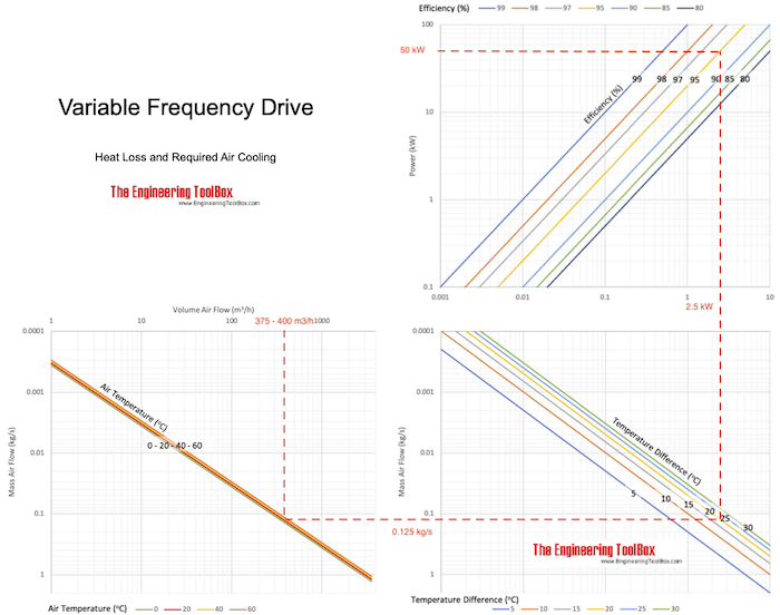
Variable Frequency Drive - Heat Loss Air Cooling Chart

Download and print Variable Frequency Drive Heat Loss Air Cooling Chart
Example - Ventilation and Cooling of a Variable-Frequency Drive
The heat generation by the variable frequency drive with maximum power of 100 kW and efficiency of 0.95,can be calculate with eq. 1 as
Hloss = (50 kW) (1 - 95 / 100)
= 2.5 kW
The mass of cooling cooling air through the cabinet when the maximum ambient operating temperature for the frequency drive is 40 oC and outside temperature of the cabinet is 20 oC can be calculated with eq. 2 as
mair = (2.5 kW) / (1.005 kJ/kg oC) ((40 oC) - (20 oC))
= 0.125 kg/s
The volume and density of air depends on the temperature of the air. The density of air at 20 oC is 1.205 kg/m3 and 1.127 kg/m3 at 40 oC.
The volume flow at the inlet (20 oC):
qair = (1 / (1.205 kg/m3)) (0.125 kg/s)
= 0.104 m3/s
= 375 m3/h
The volume flow at the outlet (40 oC):
qair = (1 / (1.127 kg/m3)) (0.125 kg/s)
= 0.111 m3/s
= 400 m3/h


