Hazardous Areas Protection Techniques for North America
Dust-ignition proof, explosion proof, instrinsically safe and nonincendive protection of hazardous areas.
Various protection techniques and methods are required for electrical installations and equipment in hazardous (classified) locations to reduce and minimize potential risk of explosion or fire.
Hazardous locations or areas in North America are in general classified according the
- Class/Division system, or the
- Zone system
Class/Division System - Protection Techniques
Protection techniques for equipment based on the Class/Division system can be summarized to
- Dust Ignition-proof
- Explosion-proof
- Intrinsically Safe
- Non-incendive
Dust-ignition proof
A dust ignition proof component prevents dust entering from outside. Arcs, sparks and heat generated inside of the enclosure will not be able to ignite the exterior surroundings near the component.
Explosion proof
An explosion proof component is capable to keep an internal explosion of a specific flammable air-vapor mixture within the component enclosure without releasing burning or hot gases to the external environment which may be potential explosive. The explosion proof equipment must also operate below safe temperatures.
The potentially sparking parts are encapsulated in a special house which is designed to prevent explosions by
- preventing the entry of hazardous material in potentially hazardous concentrations
- encapsulate potential hazardous materials in a encapsulation chamber capable to contain any explosion or fire, preventing to spread outside the chamber causing secondary explosions
Intrinsically Safe
An intrinsically safe component is incapable of releasing sufficient electrical or thermal energy to cause ignition of a specific hazardous substance under normal or abnormal (fault) operating conditions. (ISA-RP12.6 - Wiring Practices for Hazardous Area Instrumentation)

In simple terms this means that intrinsically safe equipment and wiring will limit electrical and thermal energy to a level below what required to cause start an explosion.
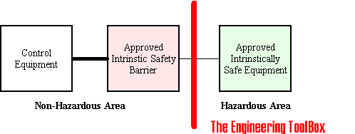
Intrinsically safe equipment operates on low power levels. Safety barriers are grounded to be effective under fault conditions and intrinsic safety is provided through voltage and current limiters. Zener diodes and resistors limiting the energy are usually mounted away from the hazardous areas. Failure to replace enclosure covers or bolts will not imperil protection.
Intrinsically safe wiring must be separated from non-intrinsically safe wiring by at least 2 inches in order to prevent the transfer of unsafe levels of energy to the hazardous area and it is vital that planning and installation of intrinsically systems are done with care and attention.
Note! Intrinsically safety can be compromised after initial installation due to improper maintenance or repair. It is important to ensure that such works are carried out properly.
Non Incendive
Non incendive components are non-sparking and incapable of releasing sufficient electrical or thermal energy to cause ignition of a hazardous substances under normal operating conditions.
Zone System - Protection Techniques
High level protection concepts with the Zone system are indicated below. The protection concepts are subdivided in several sub classes.
Encapsulated
Protection applied by encasing the components in a resin type material.
The protection is referred to as "Ex m".
Sub divisions ma for Zone 0 and mb for Zone 1.
Flameproof
The enclosure can withstand the pressure developed during an internal explosion of an explosive mixture. The explosion is not transmitted to the explosive surrounding atmosphere and the enclosure operates with a temperature to low for the surrounding explosive gas or vapor to ignite.
This protection is referred to as "Ex d".
Intrinsically Safe
Electrical equipment is under normal or abnormal conditions incapable of releasing sufficient electrical or thermal energy to cause a ignition of the hazardous surrounding atmospheric mixture.
This protection is referred to as "Ex i".
Sub divisions ia for Zone 0, ib for Zone 1 and ic for Zone 2.
Increased Safety
High quality and very robust components. Various measures are applied to reduce the probability of excessive temperatures and the occurrence of arcs or sparks in the interior and on the external parts of the equipment. Increased safety may be used with flame-proof type of protection.
The protection is referred to as "Ex e".
Oil Filled
Protection applied by submerging the components in oil.
The protection is referred to as "Ex o".
Pressurized/purged
Protection applied by keeping a positive pressure in the enclosure relative to the surrounding atmosphere with air or an inert gas. With an overpressure monitored, maintained and controlled - the surrounding ignitable atmosphere can not come in contact with energized parts of the apparatus.
The protection is referred to as "Ex p".
Sub divisions px or py for Zone 1 and pz for Zone 2.
Sand/Powder/Quartz Filled
Protection applied by covering the components with sand, powder or quartz.
The protection is referred to as "Ex q".
Non Incendive
A protection applied to electrical equipment in such a way that normal operation is not capable of igniting surrounding explosive atmospheres.
The protection is referred to as "Ex n".
Special Protection
Any method which can be shown to have the required degree of safety.
The protection is referred to as "Ex s".
Temperature Codes
The temperature code of a product denotes the maximum surface temperature of the product. Surface temperature of equipment in hazardous areas must be below the self-ignition temperature of the surrounding atmosphere.
| Temperature Code | Maximum Surface Temperature | |
|---|---|---|
| oF | oC | |
| T1 | 842 | 450 |
| T2 | 572 | 300 |
| T2A | 536 | 280 |
| T2B | 500 | 260 |
| T2C | 446 | 230 |
| T2D | 419 | 215 |
| T3 | 392 | 200 |
| T3A | 356 | 180 |
| T3B | 329 | 165 |
| T3C | 320 | 160 |
| T4 | 275 | 135 |
| T4A | 248 | 120 |
| T5 | 212 | 100 |
| T6 | 185 | 85 |
Example - Temperature Code
A product with temperature code T3 has a maximum surface temperature below 200 oC - provided it is operated within the ambient temperature specified by the manufacturer.
EPL - Equipment Protection Level - Markings
The Equipment Protection Level - EPL - marking indicates the protection level for equipment in hazardous areas. The marking differentiates between explosive gas atmospheres, explosive dust atmospheres and the explosive
atmospheres in mines susceptible to firedamp.
Class/Division System
Approved equipment is marked according rated Class (I, II, or III), Division (1 or 2), Group (A, B, C, D, E, F, or G) and temperature code (T1 through T6). For intrinsically safe equipment the words “Intrinsically Safe” or “IS” precedes the actual approval marking.
Example - Class/Division System, EPL marking
- Class I Division 1 Group B,C,D T3
- CL I Div 2 GP ABCD T3
- Intrinsically Safe Class I Division 1 Group B,C,D T3
- IS CL I Div 2 GP ABCD T3
Zone System
Approved equipment is marked according to the designed protection concept (Ex i, Ex d, Ex n and etc.), the group (I, IIA, IIB, IIC, IIIA, IIIB or IIIC) and temperature code (T1 through T6). For the United States it will be preceded by approved Class and Zone.

Example - Zone System, EPL marking
- Ex ia IIC T3
- Class I Zone 2 AEx nC IIC T5
Approval Agencies
Electrical equipment for use in hazardous areas need to be certified by an approval agency.
In North America certification is provided by
- Factory Mutual - An approval agency primarily concerned with insurance underwriting
- Underwriters Laboratories - An independent, not-for-profit product safety testing and certification organization
- Canadian Standards Association - A not-for-profit membership-based association serving business, industry, government and consumers in Canada developing standards addressing public safety and health


