Capacitors
Capacitors and capacitance - charge and unit of charge.
A capacitor is a device used to store electrical energy.

The plates of a capacitor is charged and there is an electric field between them. The capacitor will be discharged if the plates are connected together through a resistor.
Charge of a Capacitor
The charge of a capacitor can be expressed as
Q = I t (1)
where
Q = charge of capacitor (coulomb, C, mC)
I = current (amp, A)
t = time (s)
The quantity of charge (number of electrons) is measured in the unit Coulomb - C - where
1 coulomb = 6.24×10¹⁸ electrons
The smallest charge that exists is the charge carried by an electron, equal to -1.602×10⁻¹⁹ coulomb .
Example - Quantity of Electricity Transferred
If a current of 5 amp flows for 2 minutes, the quantity of electricity - coulombs - can be calculated as
Q = (5 A) (2 min) (60 s/min)
= 600 C
or, in electrons:
(600 C) (6.24×10¹⁸ electrons / C)
= 3.744×10²¹ electrons
Capacitor Charging Process

The charging process of a capacitor can be expressed as
Ucapacitor = U0 (1 - e-t/τ) (1)
where
Ucapacitor = capacitor voltage (V)
U0 = charging voltage (V)
t = time (ms)
τ = R C = time constant (ms)
R = resistance in the capacitor circuit (Ω)
C = capacitance of the capacitor (μF)
I = (U0 / R) e-t/τ (2)
Electric Field Strength (Dielectric Strength)

If two charged plates are separated with an insulating medium - a dielectric - the electric field strength (potential gradient) between the two plates can be expressed as
E = U / d (3)
where
E = electric field strength (volts/m)
U = eletrical potential (volt)
d = thickness of dielectric, distance between plates (m)
Example - Electric Field Strength
The voltage between two plates is 230 V and the distance between them is 5 mm . The electric field strength can be calculated as
E = (230 V) / ((5 mm) (10-3 m/mm))
= 46000 volts/m
= 46 kV/m
Electric Flux Density
Electric flux density is the ratio between the charge of the capacitor and the surface area of the capacitor plates:
D = Q / A (4)
where
D = electric flux density (coulomb/m2)
A = surface area of the capacitor (m2)
Charge and Applied Voltage
Charge in a capacitor is proportional to the applied voltage and can be expressed as
Q = C U (5)
where
C = constant of proportionality or capacitance (farad, F, µF)
A farad is an enormous capacitance so it is common to deal with microfarads (μF), nanofarads (nF) or picofarads (pF).
Capacitance
From (4) the capacitance can be expressed as
C = Q / U (6)
One farad is defined as the capacitance of a capacitor when there is a potential difference across the plates of one volt when holding a charge of one coulomb.
It is common to use µF (10-6 F) .
Example - Voltage over a Capacitor
A 5 µF capacitor is charged with 10 mC . The voltage across the capacitor can be calculated by modifying (4) to
U = Q / C
= (10 mC) (10-3 C/mC) / ((5 µF) (10-6 F/µF)
= 2000 V
= 2 kV
Absolute Permittivity
The ratio of electric flux density to electric field is called absolute permittivity - ε - of a dielectric and can be expressed as
ε = D / E (7)
where
ε = absolute permittivity (F/m, farad/m)
The absolute permittivity of free space or vacuum - also called the electric constant - ε0 - is 8.85×10⁻¹²F/m .
Relative Permittivity
Relative permittivity - also called the dielectric constant εr - is the ratio between the flux density of the field in an actual dielectric - ε - and the flux density of the field in absolute vacuum - ε 0.
εr = ε / ε 0 (8a)
The actual permittivity can be calculated by transforming (7a) to
ε = εr ε 0 (8b)
Parallel Plate Capacitor
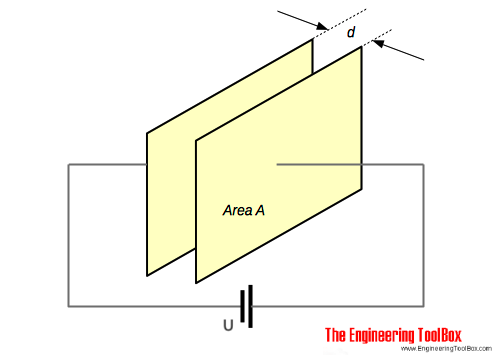
The capacitance of a plate capacitor - as shown in the figure above - is proportional with the area A of the plate. The capacitance can be expressed as
C = εr ε0 A / d (9)
where
A = area of plate (m2)
d = thickness of dielectric, distance between plates (m)
For a plate capacitor with multiple plates the capacitance can be expressed as
C = εr ε0 A (n - 1) / d (9b)
where
n = number of plates
Example - Capacitance of a Plate Capacitor
The capacitance of a plate capacitor with area 5 cm2, 10 plates and distance 0.1 mm between the plates - with ceramic dielectric with relative permittivity 30 between the plates - can be calculated as
C = (8.85×10⁻¹²F/m) (30) (5 cm2) (10-4 m2/cm2) (10 - 1) / ((0.1 mm) (10-3 m/mm))
= 11×10-9F
= 11 pF
Typical commonly used Capacitors
Typical capacitors are
- variable air capacitors
- mica capacitors
- paper capacitors
- ceramic capacitors
- plastic capacitors
- titanium oxide capacitors
- electrolytic capacitors
Capacitor as Frequency-dependent Resistor
Since a capacitor looks like a short circuit at higher AC frequencies - capacitors can be considered as simply frequency-dependent resistors that allow you to make frequency-dependent voltage di-
viders.


