Engineering ToolBox - Resources, Tools and Basic Information for Engineering and Design of Technical Applications!

BFD - Block Flow Diagram

A Block Flow Diagram is a schematic illustration of a major process.

Sponsored Links

Rectangles in Block Flow Diagrams represents unit operations. Blocks are connected by straight lines representing process flow streams.

Process flow streams may be mixtures of liquids, gases and solids flowing in pipes or ducts, or solids being carried on a conveyor belt.

To make clear, easy to understand and unambiguous block flow diagrams - a number of rules should be followed:

  • unit operations such as mixers, separators, reactors, distillation columns and heat exchangers are usually denoted by a simple block or rectangle
  • groups of unit operations may be noted by a single block or rectangle
  • process flow streams flowing into and out of the blocks are represented by neatly drawn straight lines. These lines should either be horizontal or vertical
  • the direction of flow of each of the process flow streams must be clearly indicated by arrows
  • flow streams should be numbered sequentially in a logical order
  • unit operations (i.e., blocks) should be labeled
  • where possible the diagram should be arranged so that the process material flows from left to right, with upstream units on the left and downstream units on the right

This figure depict a very small and simplified BFD:
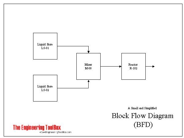
Block Flow Diagram - BFD

Example - Block Flow Diagram

Sponsored Links

Related Topics

  • Design Strategies

    Piping systems design strategies - documentation, P&ID, flow diagrams - capacities and limits.
  • Documentation

    Documentation of process control systems - Block Flow Diagrams (BFD), Process Flow Diagrams (PFD), Piping and Instrumentation Diagrams (P&ID) and more
  • Drawing Tools

    2D and 3D engineering drawing tools.
  • Process Control

    Instrumentation and process control systems - design and documentation.

Related Documents

Sponsored Links

Engineering ToolBox - SketchUp Extension - Online 3D modeling!

3D Engineering ToolBox Extension to SketchUp - add parametric components to your SketchUp model

Add standard and customized parametric components - like flange beams, lumbers, piping, stairs and more - to your Sketchup model with the Engineering ToolBox - SketchUp Extension - enabled for use with older versions of the amazing SketchUp Make and the newer "up to date" SketchUp Pro . Add the Engineering ToolBox extension to your SketchUp Make/Pro from the Extension Warehouse !

Translate this Page

Translate this page to Your Own Language .

About the Engineering ToolBox!

Privacy Policy

We don't collect information from our users. More about

Citation

This page can be cited as

  • The Engineering ToolBox (2003). BFD - Block Flow Diagram. [online] Available at: https://www.engineeringtoolbox.com/bfd-block-flow-diagram-d_467.html [Accessed Day Month Year].

Modify the access date according your visit.

close

3D Engineering ToolBox - draw and model technical applications! 2D Engineering ToolBox - create and share online diagram drawing templates! Engineering ToolBox Apps - mobile online and offline engineering applications!

Unit Converter


9.19.12

Sponsored Links
.